GaInSn experiments
As working fluid, we use MCP11 alloy which is GaInSn, a eutectic alloy of gallium, indium and tin. Besides being liquid at room temperature, it has the advantage of not being toxic making its handling easier. However, GaInSn is corrosive to some metals, e.g. aluminum.
GT2 experiment alias ZUCCHINI
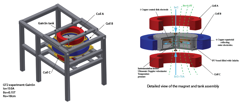
ZUCCHINI (ZUrich Cylindrical CHannel INstability Investigation) is an experiment to study liquid metal flow driven by an electrical current under the action of a magnetic field. By construction, the driving of the flow in the modified annular channel is predominantly azimuthal. A protruding inner electrode leads to a free shear layer which is a main feature of our setup differentiating it from previous studies.
Goals of ZUCCHINI
- Validate the current injection driving mechanism (stability and robustness)
- Test the Doppler and potential probe diagnostic system
- Validate the scaling laws of the zonal induced flow
- Characterize the stability diagram of the system
Experimental setup
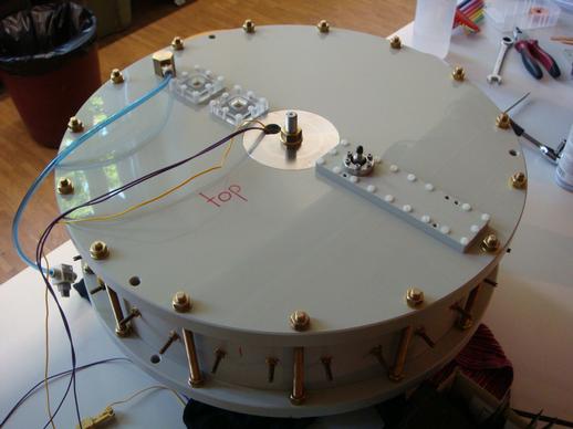
For ZUCCHINI, we adopt a pancake shape that allows us to reproduce the typical dimension characterising the current path and to optimize the forcing by maximizing the region where the Lorentz forces act with a moderate net volume of GaInSn. The tank is made of Polypropylene (PP). PP being an insulator eliminates electrical pathways outside of the liquid metal. The radius of the tank is 205 mm, the height is 100 mm.
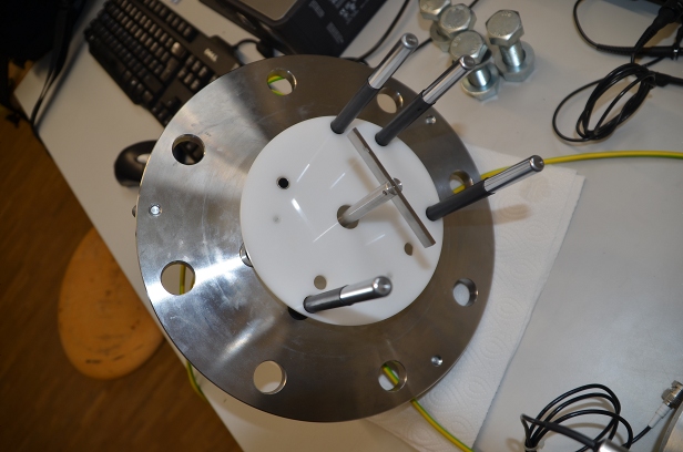
The current is injected from a central disk electrode (R= 150 mm, h= 10 mm) and collected on 6 electrodes on the side wall. A central cylindrical sleeve contains to ultrasonic Doppler velocimetry (UDV) probes from external page Signal Processing to diagnose the flow. Another UDV probe, sitting in the bottom plate, is measuring axial velocities. In addition, we use potential difference probes (PDP) in the top plate. The potential differences are recorded by a DAQ from external page National Instruments with a resolution of the order of 0.1 uV and flexible sampling rate.
All electrodes have been coated with a 20 um bonding layer of nickel and a 2-3 um corrosion protection layer of chromium. Connected to the electrodes of the current injection system are 3 to 6 switched mode low noise 50 A power supplies from external page Delta Elektronika.
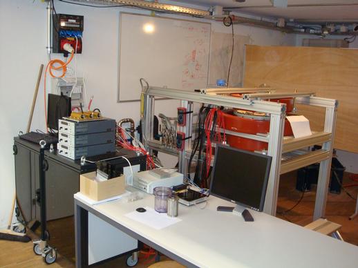
The vessel sits at the center of the magnet assembly which was either a resistive system from external page CAYLARor a superconducting coil from external page Cryomagnetics. The Caylar system consists of 3 water-cooled resistive coils with a combined center field strenght of 0.1 Tesla. The central magnet coil has a bore of 600 mm whereas the two lateral magnet coils have a bore of 400 mm each. All magnet coils are powered by linear 4-quadrant low-noise 400 A power supplies from Caylar with a total electrical output power of 10.4 kW. The Cryomagnetics coil is helium cooled, has a bore of 600 m and reaches 1 Tesla.
The liquid metal GaInSn is kept under an argon pressure of 0.2 bar at all times. In this way, we prevent it from oxidizing, and also have a simple way of filling and emptying the ZUCCHINI tank.
Main results
With ZUCCHINI, the first liquid metal experiment in our lab, we have gained a lot of experience in handling liquid metals, and measuring their flow. We found that the way of cleaning the tank and the subsequent filling procedure are crucial ingredients to a successful operation. With the argon system, we were able to take high-quality measurements for more than a year without interruption. The velocity measurements by UDV and PDP are reliable and very useful. An important point here as well as at the electrodes is the wetting of the surface.
The electrically forced MHD flow in ZUCCHINI reached Hartmann numbers M up to 2000 and Reynolds numbers Re above 200.000. Numerical simulations using the finite element method were used to complement the experimental insights in the lower parameter range. At low forcing, we found the dominantly azimuthal base flow to agree well with a asymptotic large Hartmann number model of Baylis and Hunt (1971). The free shear layer at the inner electrode scales inversely with the square-root of the Hartmann number as standard Shercliff layers.
At larger forcing, the flow becomes unstable with several distinct regimes observable. The first instability occurs at the free shear layer, and consists of counterrotating vortices traveling with the mean flow, similar to a Kelvin-Helmholtz mechanism. With increasing forcing, the vortices grow and suddenly become energetically significant compared to the base flow. This transition is governed by Re/M and might be associated with an unstable Hartmann layer. When Re/M^2 reaches order of unity, we observe that the mean velocity does not grow at the same rate as before due to higher dissipation in the system. This might be the transition from an MHD to a purely hydrodynamic regime.
It will be interesting to see how the experience and the results of ZUCCHINI compare with the rotating case, materialized in the liquid sodium experiment SpiNaCH.
Relevant publications
The GT-1 experiment
Galinstan Tank 1 (GT1) is our first liquid metal experiment. It was designed to test the current injection system and the ultrasonic Doppler velocimetry as well as to get information on corrosion in Galinstan.
Goals
- Test the power supply for the current injection system.
- Validate a protocole for ultrasonic Doppler velocimetry measurements. (Effect of oxides).
- Test the compatibility of GaInSn with different coating on the electrodes
Experimental Setup
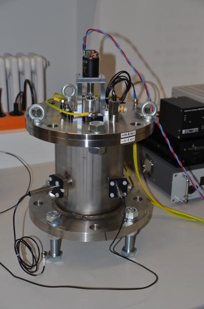
GT-1 is a cylinder with an inner diameter of 153 mm and a height of 208.5 mm. It is made of 316 stainless steel in order to be inert to both, Galinstan and sodium. GT-1 is filled with MCP 11 alloy supplied by external page 5N Plus UK Ltd. A small overpressure of Argon is applied to this experiment to avoid the excessive oxidation of the GaInSn.
The injection system for the electrical current consists of four copper electrodes. The electrodes were first coated with 20 um nickel and 2-3 um of chromium on top of that (J.T. Eriksson - PhD Thesis in Acta Polytechnica Scandinavica, El 48, 1982). The chromium coating has a relatively small corrosion rate and it improves the wetting properties necessary for a good electrical coupling.
In addition, a small motor with a straight propeller is provides stirring capability.
We use ultrasonic Doppler velocimetry (UDV) to measure velocities in the fluid. The UDV system is a DOP 3010 from Signal Processing SA with three transducers. Every transducer records a profile of the velocity component in the direction of the ultrasonic (US) beam it emits. For UDV in order to work, the fluid needs to contain particles that reflect the US waves. Velocities are determined from the back-scattered signal through the Doppler shift it has acquired through the motion of the scatterer. Depth is attributed to the different measurement points through the travel time of the signal.
Main results
- It is straightforward to use UDV in water when seeding it with particles that are small enough and floating in order to follow the fluid velocity. However, it turns out that it is not as easy to get reliable UDV measurements in Galinstan because of problems with oxides and with wetting the US probes.
- We have successfully tested a power supply from external page Delta Elektronika and its interplay with the UDV system in GT1 for use in GT2. Moreover, we have conducted resistance measurements in Galinstan. It appears that the chromium-coated copper electrodes are a good choice of material since they are not corroded over time scales of weeks. The wetting with Galinstan can be improved by thoroughly degreasing the surface. Efficient cleaning procedures include the use of WD-40, a penetrating oil, followed by a treatment with Isopropanol for degreasing.
UDV measurements have up to now been successful in water. The testing of the UDV system in Galinstan is still ongoing.
Perspectives
- We plan to perform the same tests using liquid sodium. Minor modification will be necessary to maintain the temperature of the device above the melting point of sodium (98C)
